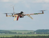
Do you like puzzles? I have one for you – It has 3 legs, 3 arms and 6 blades? Can you guess what am I talking about?
No, it is not any sort of failed genetic experiment. I am talking about tricopter.
I have been interested in flying machines without fixed wing for quite a long time. Classical heli models are however quite complex mechanical machines that are easy to damage. Helicopter’s control is quite different from control of fixed wing plane. So I expected the classical beginner’s phase – 1 takeoff = 1 crash. Almost every damage of heli usually results in long wait for replacement parts. And that is nothing to look for. And of course I like building things my way, which is not possible in heli sector. Just try to guess how many people are able to build swash plate at home from scratch. These are the aspects that held me from heli bussines for long time.
One day I encountered video with tricopter. I think it was first version of tricopter described at rcexplorer.se. I was astonished by this configuration instantly. I have been aware of quadrocopters for some time before, but three motor copter has interesting, simple and fresh look that I really like. You can also design and build own copter at home yourself to express some of your creativity. Classical helicopters seems to me all the same and I find this same look boring. Good designed n-copter has even more advantages over heli. It is very durable and nearly every damage can be easily repaired at home. These are the reasons that determined my next task in RC hobby.
Components selection
At the beginning I wasn’t sure what parameters of components are significant for tricopter. I was picking ESCs and motors simply according to price and user reviews on hobbyking.com. At the end I chose Hobbyking SS Series 18-20A ESCs and FC 28-22 Brushless Outrunner 1200kv motors.
Soon in real use I discovered that it wasn’t best choice. Motors have too many revolutions per Volt so relatively small inefficient propellers are required. Today I would probably choose hexTronik DT750. ESCs performed relatively well, but as soon as I decided to reflash their firmware to improve copter stability I found that programming pads are missing on ESC’s PCB. I had to solder wires directly to SMD chip. This is quite challenging task and I accidentally killed one of the ESCs during process. So when choosing motor for copter go for low rev. per Volt. For ESC pick up one with external oscillator and programming pads in following list or browse related discussion on rcgroups.com for more information. Today should be also possible to buy already flashed ESCs.
Control board selection was much easier. Available options in that time were only KK board, arduino with Wii senzors, and separate gyros. So I chose HK-KK-v2.1 as the simplest solution.
Today there are many more advanced boards to buy. This board however works well for me and I don’t have reason to change it. There is only one flaw I am aware of – piezogyros temperature drift. So today I would probably choose board with modern MEMS gyro instead. This sort of boards is good for people that enjoy “controlling” the tricopter during flight. If you want your tricopter just to fly itself with minimal interaction you must choose more advanced boards with accelerometers, barometer, magnetometer and GPS. However it seems to me bit boring when all the work does computer on board.
Last item on list was servo for yaw mechanism. I used 9g HXT900 servo for quite a long time simply because it was laying on my table during build. Still it was only matter of time to brake plastic gears in servo. After one of my rough landing servo gears were damaged. Therefore I ordered more suitable 12g digital servo with metal gears. This servo works well up today.
Frame construction
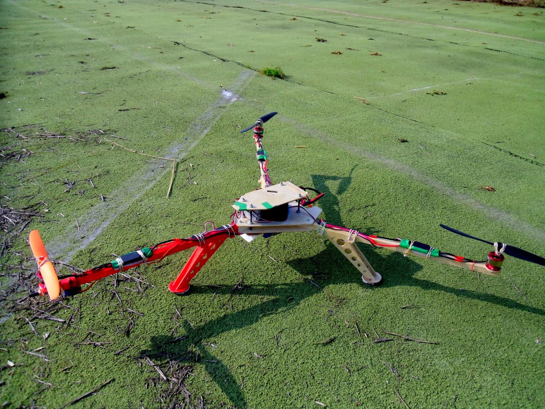
During week I have to attend to university in Brno where I don’t have room for any serious work on my planes. Therefore I spent quite a lot of time on frame design to simplify construction itself. I already had CNC router available so the design was performed on computer and the build itself was only about cutting parts on CNC and putting them all together. The result of computer design and final realization are shown on pictures below. It may look weird but it was designed to carry FPV set so the esthetical aspects had low priority.
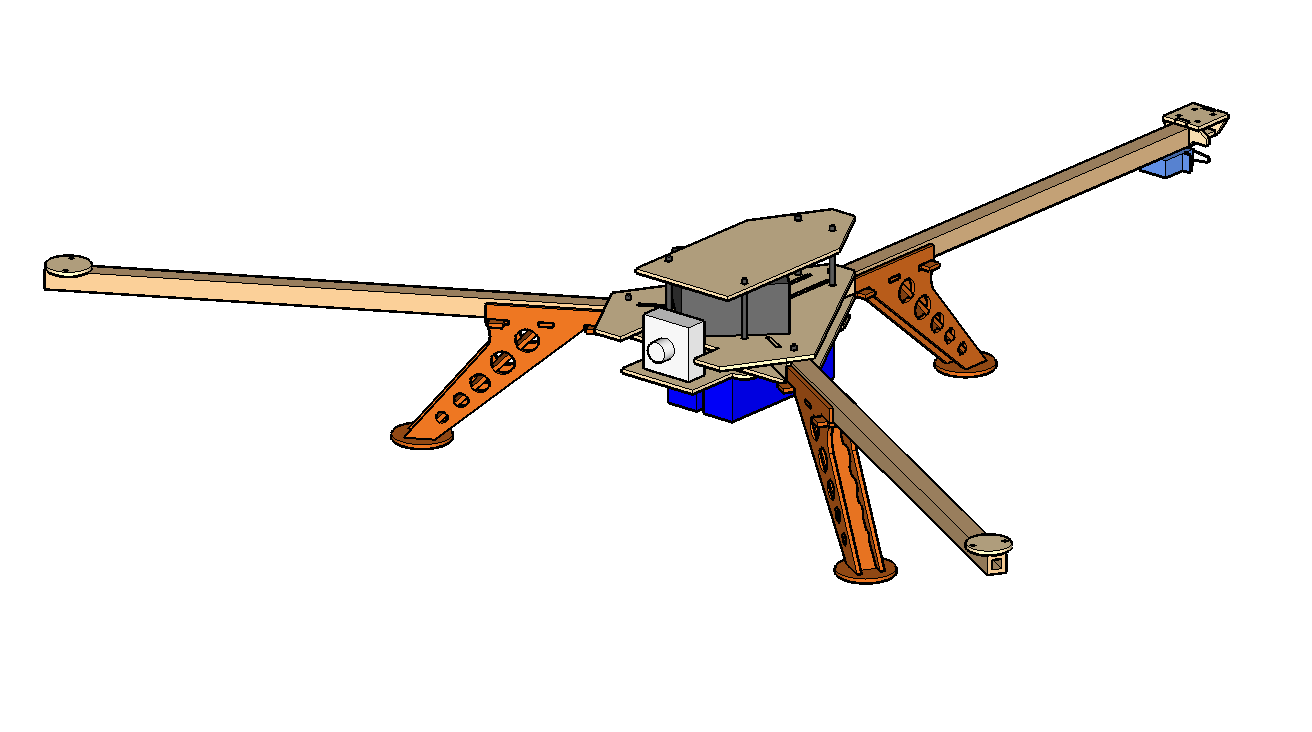
The frame consists of central platform, 3 replaceable arms, and 3 separate landing legs. Arms are glued from wooden beams 10x3mm to create 13x13mm hollow prism. This solutions brings lower weight and more strength than solid arms. Each arm is tied to central platform using 2 screws and can be easily replaced in case of damage. One aspect of design I am proud of is possibility to rotate front arms after removing outer screw. This significantly reduces required space during transfers.
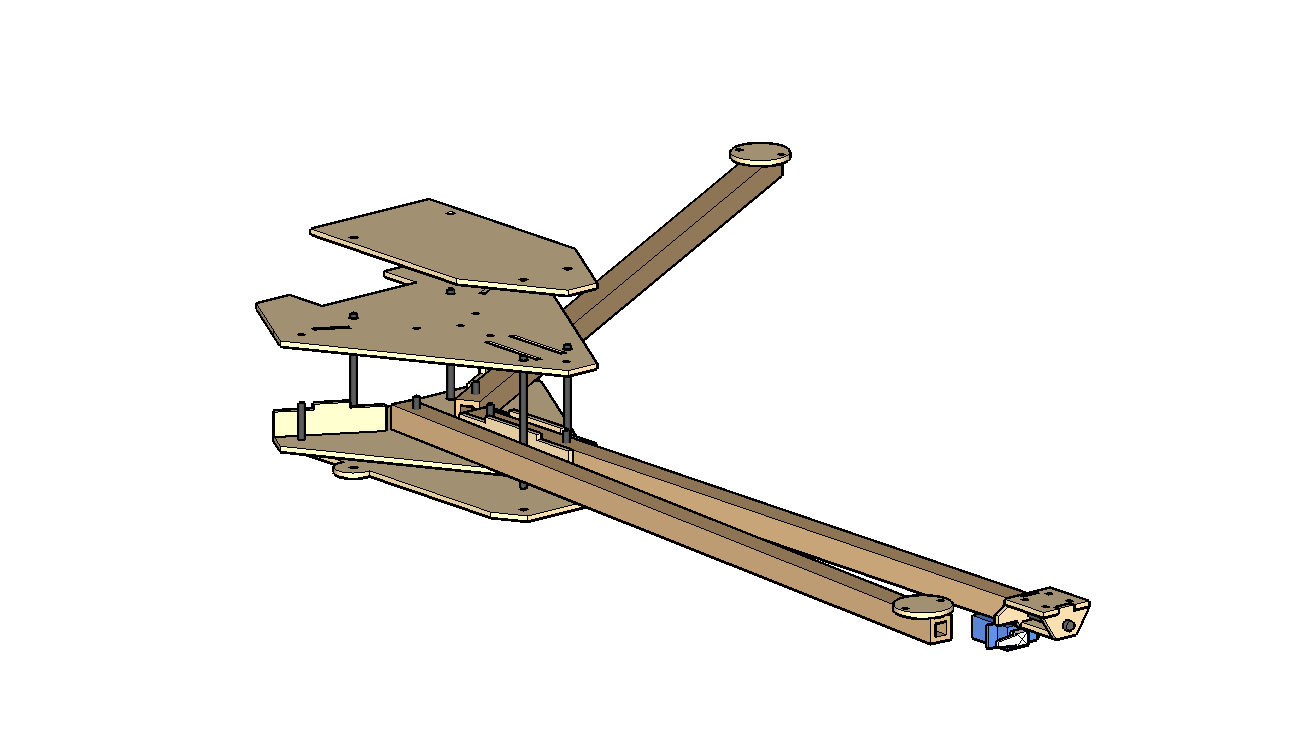
Central platform is cut from 3mm plywood. Main part that holds all the arms is glued together. Lower battery holder and top protective sheet are screwed on 4mm threaded rods. This allows simple adjustments of room for on board electronics and also makes possible to change parts in case of damage.
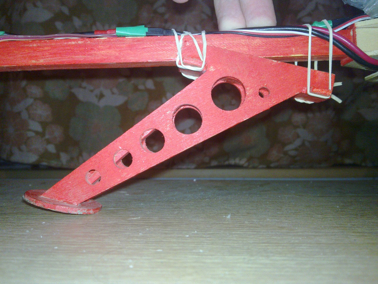
Another idea I am proud of is landing gear system. Landing legs are stick to arms using rubber ties. Shape of legs have been clever designed to bend on rubber ties to suppress shocks during hard landing and crashes. Described system survived uncontrolled crash from about 20 meters with only minor damage. Legs also create large base which prevents rolling over side. There may be simpler and lighter approaches but I like this system very much :-).
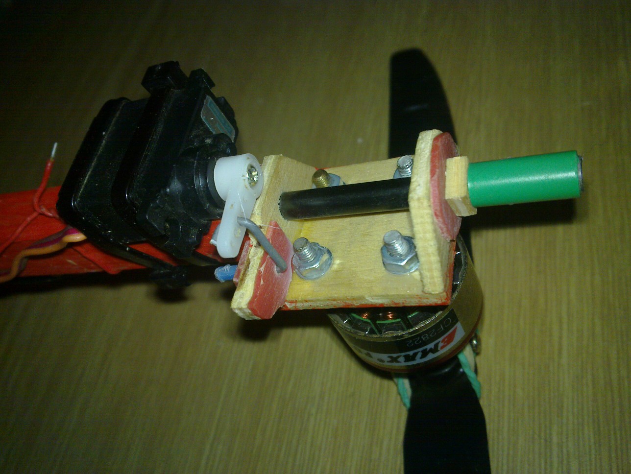
Most complicated part on tricopter frame is yaw mechanism. You can find some ideas on rcexplorer.se website, that inspired me to build tricopter. I however chose my own way to build yaw. I used the hollow arms and glued 5mm diameter carbon tube in the end of rear arm. This is the tube that rear motor holder is rotating around. Lower left is displayed computer design (top view) and lower right is realization (bottom view). I also added some plastic “bearings” to prevent deformation of plywood.
Electronics and final thoughts
Attaching and wiring components was simple task. Extended supply wires from ESCs were soldered together and fitted with battery connector. Servo connectors from servo and ESCs were guided through servo extensions to control board. Similarly the inputs from receiver were connected using male-male servo cables to control board. Only thing left was to charge battery and go for first fly.
First flights showed that all screws are getting loose because of vibrations. It was necessary to secure them using some sort of glue. To be sure I also secured all connectors using adhesive tape. The control board gain tuning took 2 flights. After that I have been flying whole season without any changes. In August 2012 I finally mounted FPV set to feel the joy of flying with well tuned tricopter.