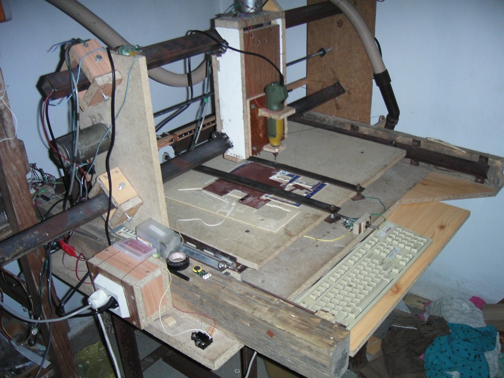
After I crashed my 2 meters wingspan CAP232 (in the middle of header image) I decided to build new improved version of own CNC machine. Computer aided design was obvious choice. So own CNC router became actual topic again.
This time a little older and more experienced I was thinking how to build CNC router again. The major requirement was good enough and repeatable precision (within few tenths of millimeter) for 3mm plywood cutting. As I was still student my budget was quite limited. Therefor I had to reduce my expenses to bare minimum and use most of material laying around. Please note that construction described in this and following articles is far from ideal approach to build CNC router. Consider it only as an example of what can be done by applying some knowledge and mechanical skills with minimal cost.
I started with search for available materials at home. I found some 35mm wooden desk and some more 18mm thick desks. Then some wooden beams from our house build and some steel square and L type rods. I also found fan from our old car with 12V motor inside and another similar size 12V motor. Together with package of bearing from several old machines I got interesting collection of material to work with.
The base of the machine is 35mm thick wooden desk. On this desk there are glued 2 wooden beams. All glued joints of wood parts are strengthened using wooden pins in pre-drilled holes. On the inner sides of the beams there are mounted 2 L type rods using screws. These rods create rails for Y axis movement. Accurate position of rails is adjusted by inserting some material between rod and beam. On each rod there are welded mounts for easier installation. Welding however resulted into steel rod deformation which was difficult to repair.
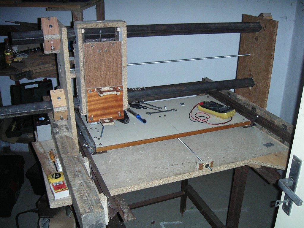
Near beams there are two desks raised. These desks have pre-cut holes for square steel rods to make rails for X axis. Rods go through both desks and are mounted using 4 screws on both sides. These screws allow to adjust rods position in range of approx. 10mm to make them exactly parallel to each other.
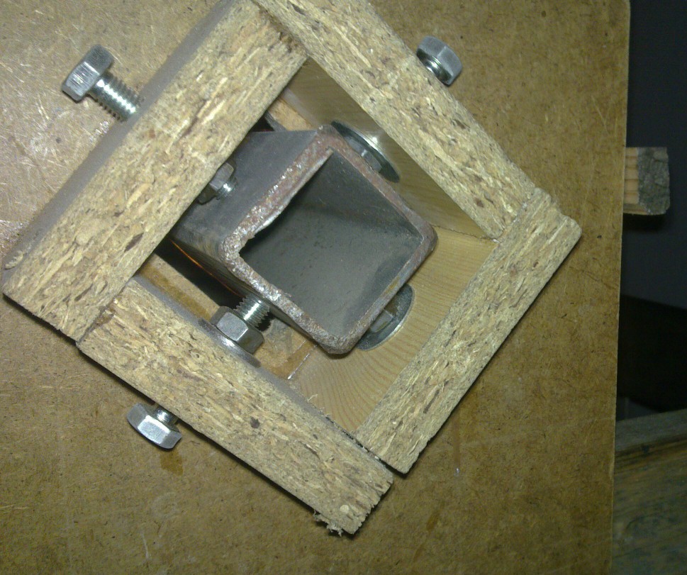
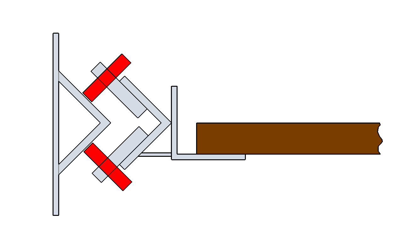
All moving parts are designed similarly. The base is wooden desk. On desk’s edges there are screwed platforms with bearings that roll on rails. These platforms are welded from 2 L shaped rods and steel strip as reinforcement. One of the rods has welded screws with fitted bearings. The other rod has mounting holes to screw on the basic wooden desk. These holes are bit bigger than screws diameter to adjust exact position according to other parts of machine. This time I was taking care to not deform steel parts during welding. Notice that there is a gap between wooden desk and vertical side of the rod. This gap and steel elasticity allows to create permanent tension that helps to reduce backslash and to accommodate minor rails inaccuracy.
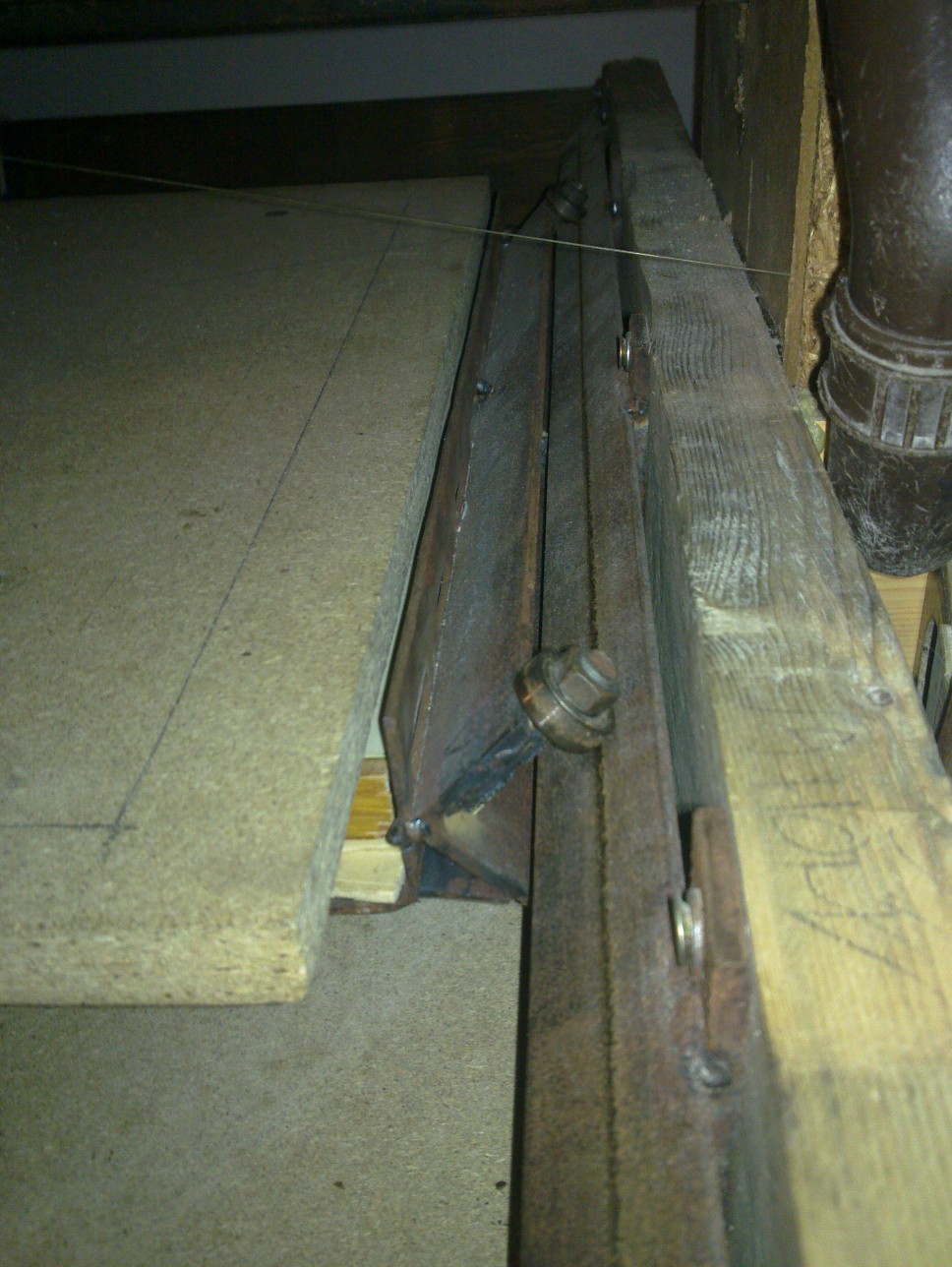
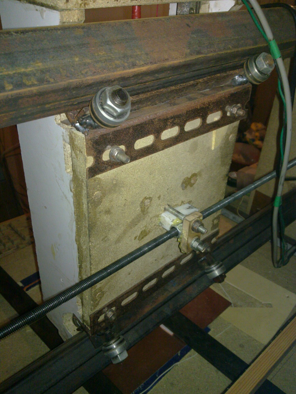
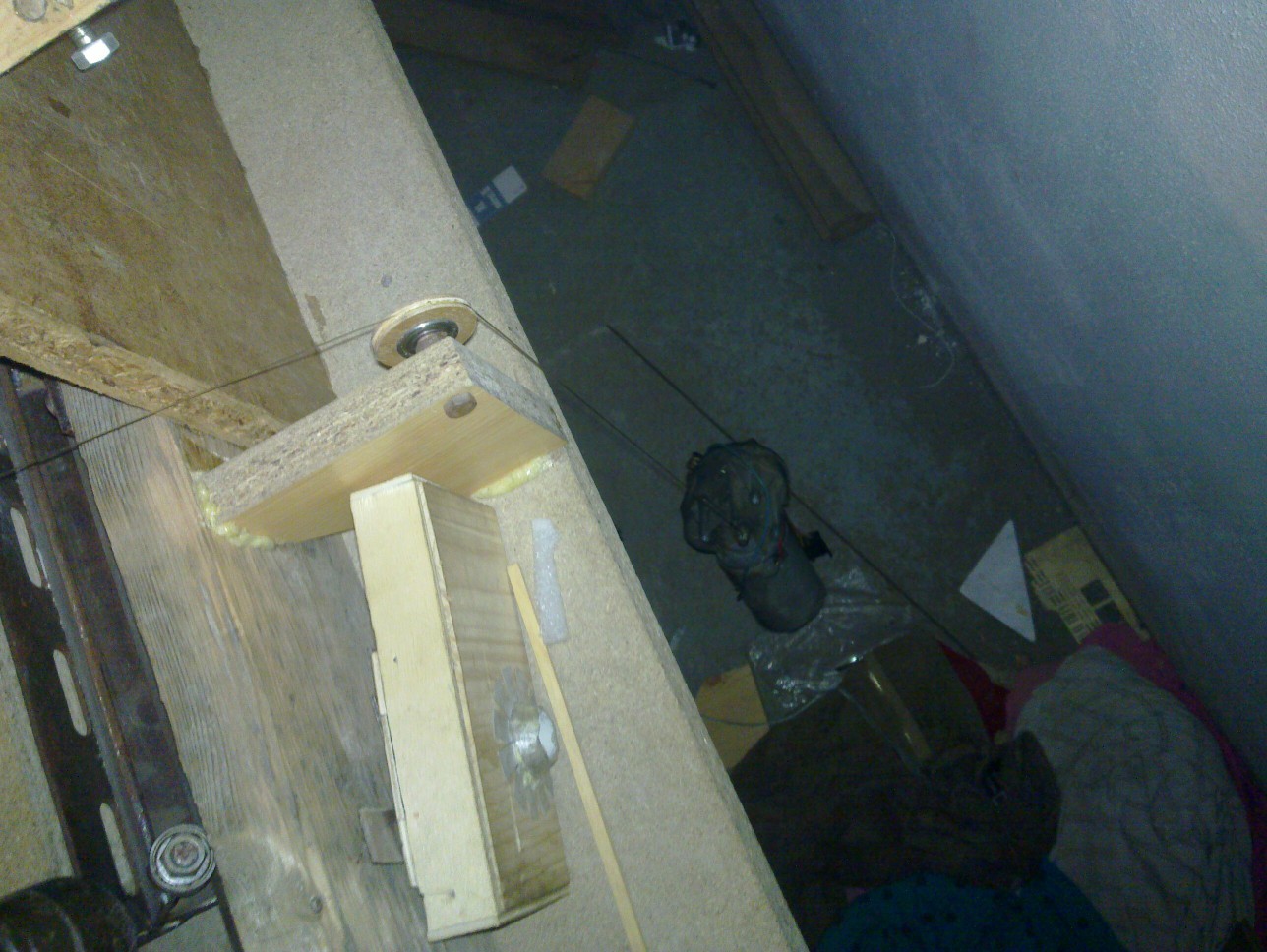
Axes movement is controlled by metric threaded rods rotation. Threaded rods are mounted in bearing on each side and driven by motors. There has been problem with backslash between metric thread and nut. In case of Y axis I wasn’t able to fit nut in precise coaxial position. It luckily eliminated backslash but still allowed free rotation. Z axis backslash is eliminated just by weight of axis with spindle. The most problematic was backslash issue for X axis. In the end I chose not really elegant but simple and sufficient solution. On the machine edge hangs a weight that forces X axis to one side. As you can see in the pictures below.
Thats quite all about mechanic aspects of my CNC router. In next article I will explain electric part of the machine – motors and drivers, spindle control and more.