When I finished mechanical construction of my CNC router it was time to make it alive using some electronic.
Each axis requires one motor to drive threaded rod. Stepper motors with acceptable moment are not cheap things. The cost climbs even higher because of required driver. Besides I don’t like the way the stepper motors are driven using open regulation loop. Higher loads can lead to lost steps and the control software doesn’t get any information about this condition.
I managed to get 2 pieces of solid 12V DC motor and one smaller motor that works on 12V reasonably well. I decided to give these motors a try to make primitive servo drive using optical rotary encoders.
Motor drivers
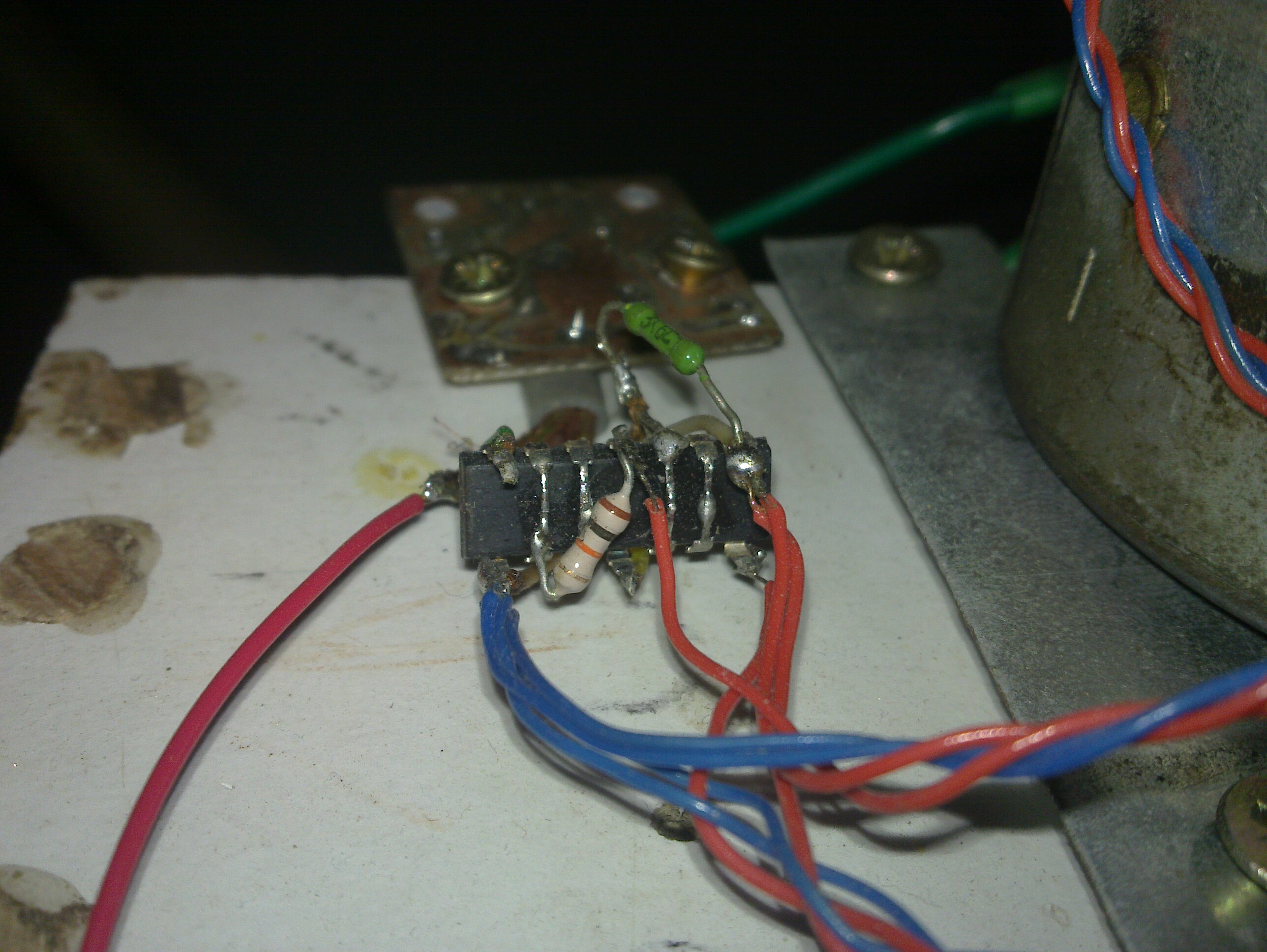
First step was to design motor drivers. Driver must be able to turn the motor in both directions or leave it off based on 5V logic inputs. To meet this requirement a full H bridge topology is used. To keep the circuit simple I chose bipolar transistors. Since the motors have quite low current consumption (around 2A per motor), worse characteristics of bipolar driver don’t make any problems. Schematic of circuit I used is shown in following picture. Please note that motor is represented by the inductor symbol and all input/output capacitors are omitted in schematic. Values of the parts are not shown because I don’t remember them. If you don’t have knowledge to compute them for yourself I recommend you to buy finished driver.
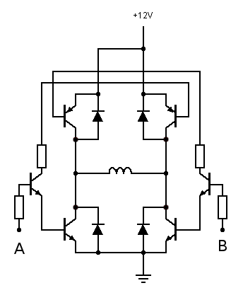
Special care must be taken to not turn on both sides of the bridge at the same time (input values AB = 11). High current flow through all 4 transistors would result in permanent damage. Valid AB input combinations are 00 – motor off, 01 – spin clockwise (CW) and 10 – spin counter clockwise (CCW).
Rotary encoders
In current state I was able to move all axes just by toggling drivers inputs. CNC however requires precise measurement of axes movements. In case of stepper motor we can get the length by calculating number of discrete steps. DC motors are not aware of how far they already went and it is necessary to add some sort of step calculator – rotary encoder. Encoder gives us information “one step CW now” or “one step CCW now”. Number of these steps tells us length of axis movement just like the stepper motor approach. I think it is not necessary to describe this principle in detail. You can find more information yourself for example on wiki .
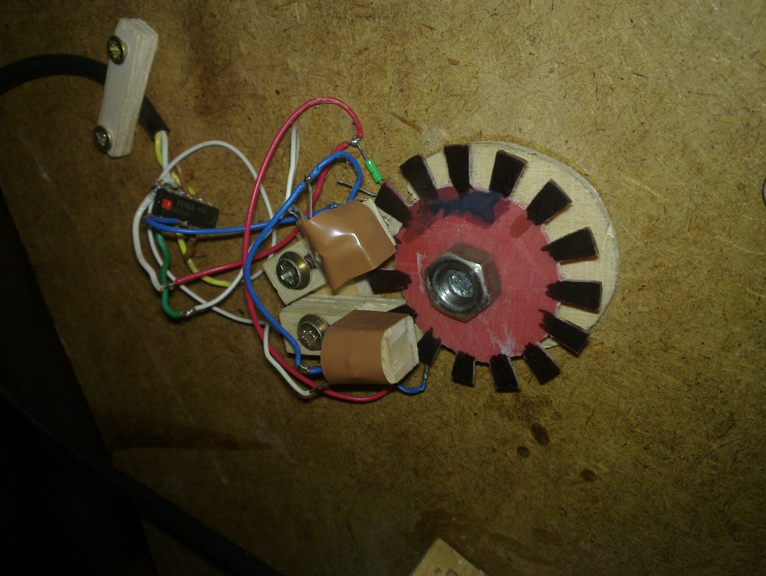
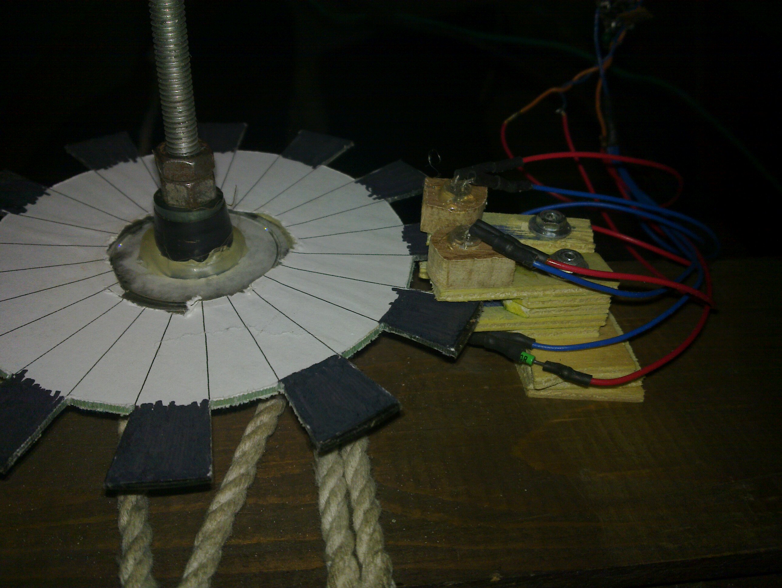
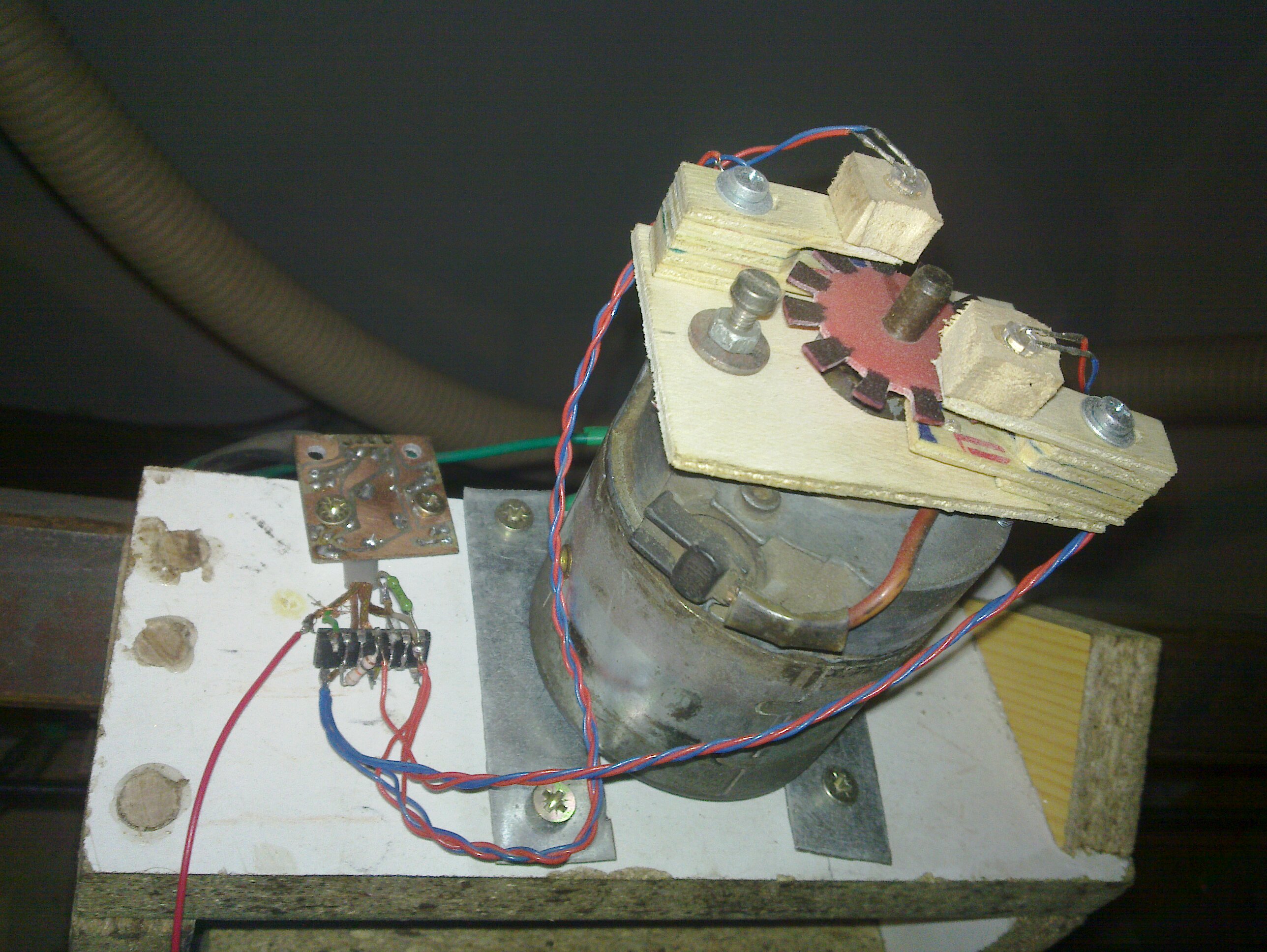
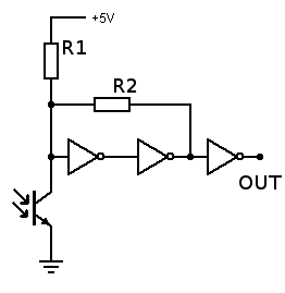
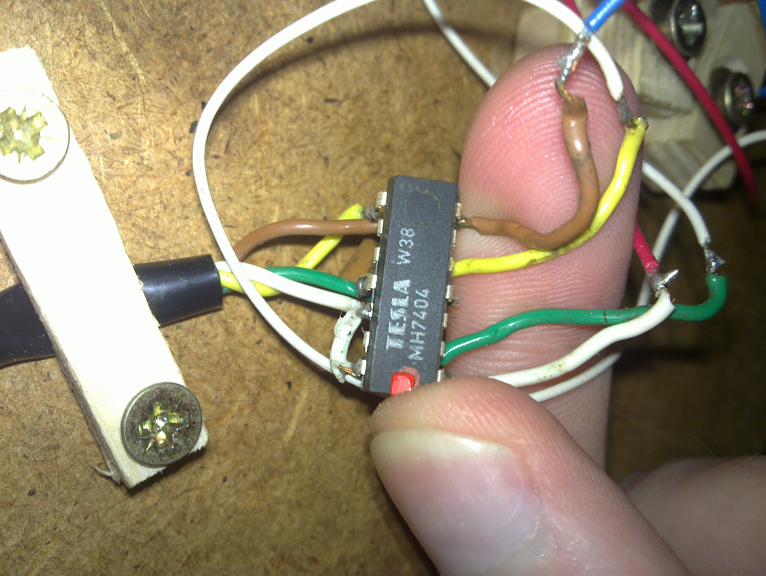
To realize encoders I chose optical principle using IR LED and phototransistors. Number of segments on encoder discs is chosen to give 48 steps per 1 millimeter according to thread steepness. First tries showed some signal bouncing on step transitions. Phototransistor output needs some adjustments using schmitt trigger composed of 3 gates of 7404 circuit. Resistor R1 defines working area of phototransistor and R2 sets amount of hysteresis. Values of both resistors need to by determined experimentally in real environment.
Control logic
It is desired to maintain compatibility with stepper motor machines – control software gives us instructions using two lines STEP and DIR. Direction of motor rotation can be controlled using two inputs of motor driver and encoder tells us how much steps we already traveled. All we have to do is is to put these things together.
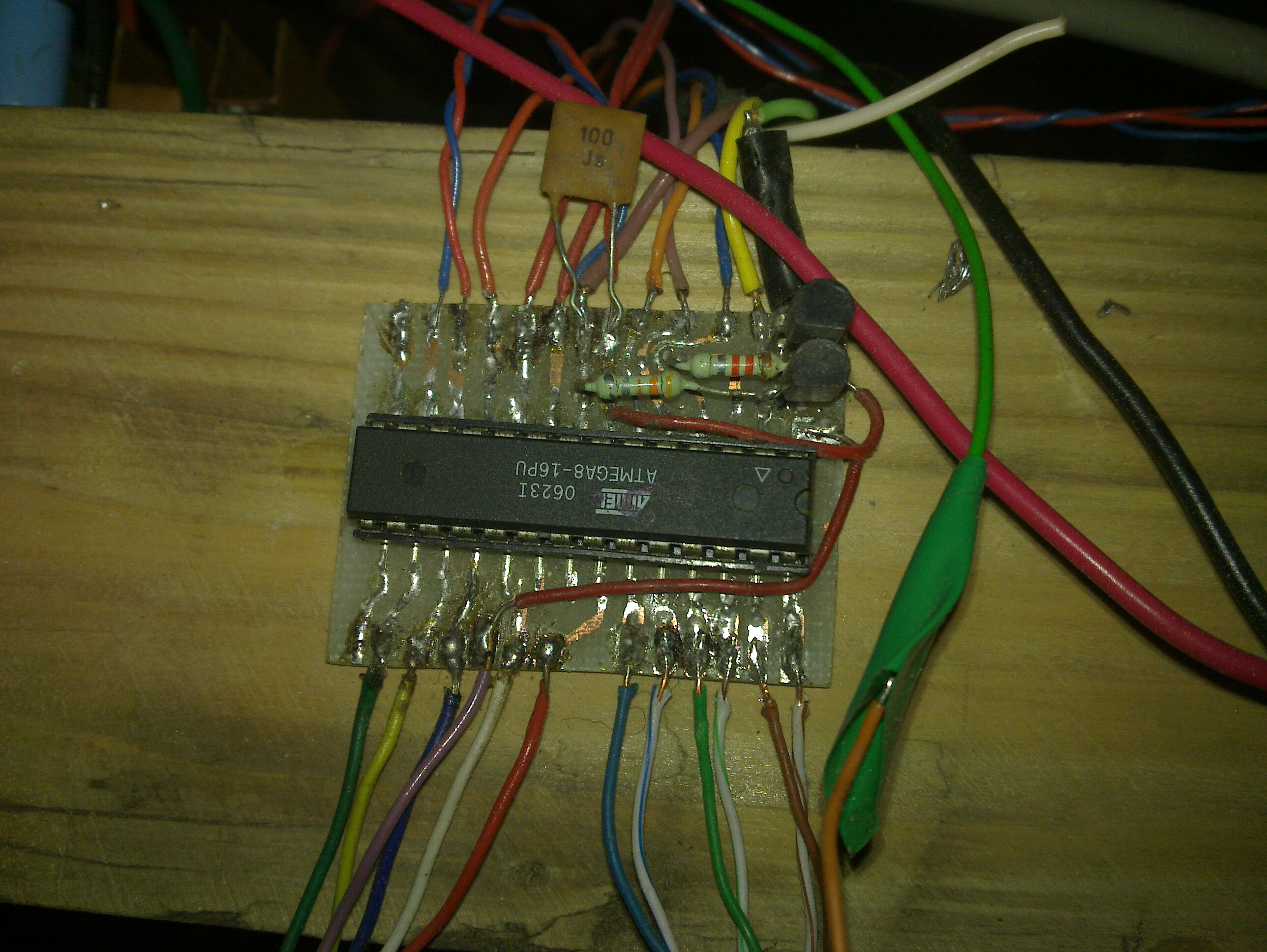
All three axes movements are driven by one ATmega8 MCU. The algorithm is quite simple. There is a signed variable for each axis. If control software gave us instruction to make one step CW the variable increments and in case of CCW step the variable decrements. If encoder detects one step CW the variable decrements and increments on CCW step detection. The variable value controls the motor rotation. If the variable value is positive the CW rotation is initiated. On negative value the CCW rotation occurs. Zero value of variable tells the motor to stop. Absolute value of variable describes how far we are from ideal path generated by computer. It is important for control software parameters setting (speed, acceleration, etc.).
Parallel port protection
Computer parallel port is quite sensitive interface and can’t be used to control external devices directly. Best solution is to use optocouplers protection. In that case there should not be possible to damage parallel port by any mistake on CNC machine. I chose simpler but less safe solution using 2 pieces of 74244 circuit. On parallel port there are 12 outputs and 5 inputs so we need two pieces of 74244 with 8 gates.
Power source
Used motors especially with described bipolar drivers don’t have high current consumption. The machine is powered by old PC AT power source that can deliver up to 8A on 12V section. Using computer power source has an advantage, because it can supply also 5V for control logic circuits.